Reflection
What happens to sound when it hits a surface?

Figure 7: Specular reflection
When sound hits a surface such as a wall or a floor, several things happen. A proportion of the sound is:
- Reflected back into the room (energy is preserved).
- Transmitted through the surface and escapes from the room (energy is lost).
- Absorbed by the surface (energy is lost).
For the purposes of our discussion, we will forget about transmitted sound. Once sound energy has escaped from the room, it is no longer part of the sound field and can therefore be ignored.
Reflection of sound

Figure 8: A virtual sound source created by
sound bouncing off a wall
The most obvious example of reflection in every day life is looking in a mirror. The silvered coating on the back of the glass provides a perfect surface off which light can bounce. This type of reflection is known as a “specular reflection”. In this type of reflection, the angle at which the light bounces off the mirror is exactly the same as the angle at which it hit the mirror.
When you look at yourself in the mirror, you see a “virtual you” staring back.
Much the same thing happens when sound bounces off a reflective wall. A loudspeaker is aimed at an angle to a wall,
then a listener faces the wall and looks at the point on the wall at which the speaker is aimed; they will perceive
the sound to be coming from a “virtual” loudspeaker on the opposite side of the wall.

Figure 9: A concave surface causes the
reflected sound to be focussed
If sound is reflected from a concave surface, then focusing occurs.
Unless this effect is deliberately required, then it causes highly undesirable effects in an auditorium. Concave
surfaces should either be avoided within a building, or made sufficiently shallow, that their focal point lies outside
the room.
Absorption
The science of architectural acoustics pays particular attention to a property that every substance possesses to some degree or another – absorption. Not only do different surfaces absorb sounds to different degrees; the absorbency of a surface varies with frequency.
The units of absorption
The absorption of a material is measured in (Metric) Sabins and represents the proportion of sound energy that a material absorbs at a particular frequency.
In order to understand absorbency, imagine you are in a room in which music is playing. As you move around the room you can hear sound coming from all directions as it bounces off the walls, floor and ceiling. But now as you stand facing an open window, you can only hear coming from the room behind you. The open window allows all the sound to escape. and at that point on the wall, you cannot here any reflections at all.
The open window can be thought of as a perfect absorber because any sound that passes through it never returns. It has been completely “absorbed”.
So now imagine our window has an area of one square metre. This would be described has having 1 Metric Sabin of absorbency. (If the word “Metric” is omitted, then it is assumed that the area is one square foot).
If one square metre of a material absorbs 28% of the incident sound energy, then it is said to have an absorption of 0.28 Metric Sabins.
Similarly, if a wall ten square metres in area absorbs 35% of the incident sound energy, then the entire wall has a total absorption of 3.5 Metric Sabins.
Absorption coefficients
It must also be understood that a particular material may be a very good absorber of high frequency sounds, but also a very poor absorber of low frequency sounds. Therefore, when quoting the absorbency of a material, it is very important that you also quote for which frequency the absorption value is relevant.
It is standard practice to quote absorbency values for at least six standard frequencies, each being an octave higher than the one before. More detailed absorbency figures are sometimes quotes across 9 octave bands.
For instance, thin carpet with no underlay on a concrete floor has the following absorbency values: The columns in grey are not always quoted.
| 64Hz | 125 Hz | 250 Hz | 500 Hz | 1 KHz | 2 KHz | 4 KHz | 8 KHz | 16 KHz |
|---|---|---|---|---|---|---|---|---|
| 0.00 | 0.01 | 0.02 | 0.06 | 0.15 | 0.25 | 0.45 | 0.61 | 0.75 |
Table 1: Absorption values for thin carpet with no underlay on concrete
As you can see, this particular thin carpet is pretty much useless for absorbing sound below 2KHz, and only moderately good above 2KHz. The absorbency only becomes appreciable at 16KHz.
If you look at the absorption value at 250Hz, you will see that it is 0.02, or 2%. Look at this the other way around—if only 2% is absorbed, then 98% of the sound is reflected. Absorption can be thought of as simply a lack of reflection. So, the mathematical relationship between reflectivity and absorption is:
Reflectivity = 1 — Absorption
Many acoustics equations use the Greek letter α (alpha) to represent absorption, and the Greek letter ρ (rho) to represent reflectivity. So you will often see the above equation quoted as:
ρ = 1 — α
Equation 8: Reflectivity equals one minus absorption
Diffusion
When sound is reflected off a surface, the texture of that surface will determine how the sound is reflected. A smooth, flat surface will create a specular reflection (see Figure 7), but a rough surface will cause the sound to be scattered. Diffusion is another name for the scattering of sound.
Simple geometrical diffusers
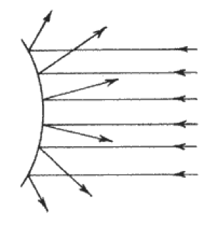
Figure 10: A convex surface causes the
reflected sound to be scattered
The simplest way to scatter sound is to use rough or convex surfaces. It has been known for many centuries that such shapes improve the quality of sound. Many of the concert halls built in the 19th century (before acoustics was a formal science), have excellent acoustics.
For instance, the Vienna Musikvereinsaal, opened in Jan 1870 is considered one of the best concert halls in the world. This was because the fashion of the day was to have many ornate carvings and plaster mouldings on the walls. These complex surfaces give the necessary diffusion to create an excellent listening environment.
Diffusers based on number theory
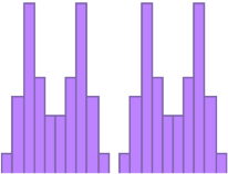
Figure 11: Cross section
through 2, period 11,
Schröder diffusers
There are many more ways to scatter sound besides using rough or convex surfaces. In addition to identifying the effective upper limit for the transition region of a sound field, Manfred Schröder invented a type of diffuser known as the Quadratic Residue Diffuser (QRD). It is formed by breaking up a wall surface into “wells” of different depth.
Schröder developed a simple mathematical equation for calculating the well depth, but reasons for why this type of diffuser works are deeply rooted in number theory. Suffice it to say that when sound is reflected off this staircase-like surface, an interference pattern is created that causes the sound to be scattered widely.
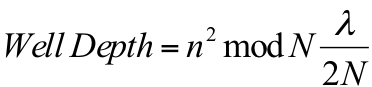
Equation 9: Well depth calculation for a Schröder diffuser
To calculate the well depths of such a diffuser, the equation 9 is used:
Where n is the well number (1, 2, 3, etc), N is a prime number that determines the total number of wells (7, 11, 13, etc), and λ is the wavelength of the design frequency.
Schröder diffusers have an effective bandwidth which ranges from half an octave below their design frequency, up to a frequency determined by the width of the wells. Manfred Schröder recommends that the well width should be set to the design wavelength multiplied by 0.137.
The efficiency of a Schröder diffuser is greatly improved if each well is isolated from its neighbours by using a thin divider.
These diffusers also a frequency limit below which they are not particularly effective. For practical purposes, this is taken to be the rooms Schröder frequency. See Equation 13.
E.G. A Schröder diffuser with a design frequency of 1415Hz will have wells 33mm wide, and will have an effective operating bandwidth from 1000Hz up to 5160Hz. The wells will range in depth from 0mm to 99mm.
This type of diffuser revolutionized the levels of diffusion that could be achieved, and has been successfully applied to many modern concert halls around the world. Examples are the Carnegie Hall in New York and the Michael Fowler Centre in New Zealand.
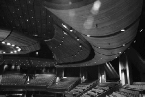
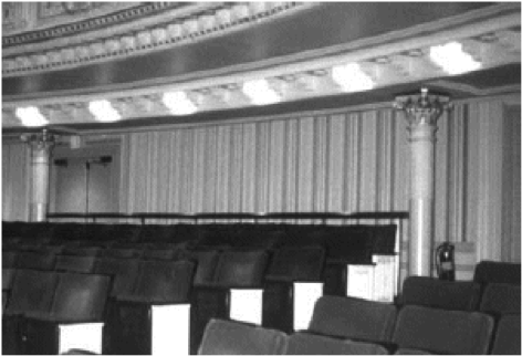
Figure 12: Schröder diffusers in the Michael Fowler Centre (left) and Carnegie Hall (right)
This type of diffuser has provided the acoustician with a powerful tool in the creation of diffusion. However, extensive research has shown that when several Schröder diffusers are placed side by side, peaks and troughs appear in their combined sound fields that actually reduce diffusion!
This behaviour occurs as a direct consequence of the periodic nature of the diffuser’s construction.
Solving the periodicity problem inherent to Schröder diffusers
Peter D’Antonio of RPG Inc in Maryland, USA, and Prof Trevor Cox of Salford University, UK have performed extensive research into how a large scale surface can be made as diffuse as possible, without introducing periodic peaks and troughs in the resulting sound field. Several solutions have been proposed, but the simplest solution is a type of flat panel known as a Binary Array or Hybrid diffuser. The term “hybrid” is used because diffusion is achieved through a carefully calculated combination of reflection and absorption.
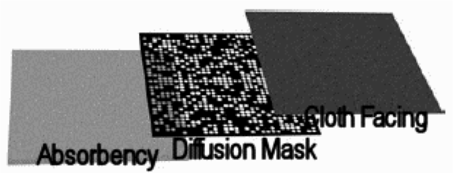
Figure 13: A hybrid diffuser
Holes are drilled in a reflective mask at carefully determined locations. The mask is then placed over an absorbent surface such as glass fibre or Rockwool. The combination of absorbency and reflectivity causes interference patterns to be created that scatter the sound. A decorative cloth facing can then be placed over the mask.
The resulting panel is defiantly simple to construct, yet the reasons for why it is such a good diffuser involve complex mathematics.
Diffraction
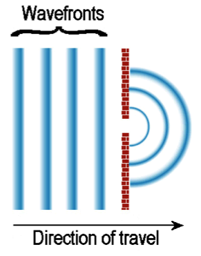
Figure 14: Diffraction of plane wave
fronts through a narrow opening
When a wave front passes from an area of restricted width into an open area, or encounters the corner of an object, the wave front changes direction. This is known as diffraction.
Diffraction typically causes a plane wave front moving in a straight line to expand in a curve.
An example of this is when sound is played in a room, and the door has been left open. As sound passes through the door opening, the wave front that was restricted by the width of the door frame, suddenly finds itself expanding into the next room. This causes the sound to be heard throughout the neighbouring room.
This effect also takes places when sound waves encounter the corner of an object.
Diffraction causes sound to bend around corners.
Refraction
When sound travels from a medium of one density into a medium of another density, the speed of sound changes. This change in speed causes the wave front to change direction. A change of direction also occurs when sound travels through an area of unequal temperature. Refraction is the change of direction caused by a change of temperature or density.
When refraction occurs, the shape of the wave front typically remains unchanged, only its direction changes.
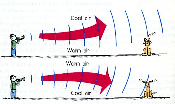
Figure 15: Refraction caused by differences in air temperature
Refraction is the effect that can cause sound to travel long distances over cool water. This effect is particularly noticeable if you are standing next to a small lake in the early morning. You can see some people on the other side of the lake, but you can’t hear anything they are saying. As the sun rises, the air temperature above the lake starts to rise, but the air at the lake surface stays cooler because of the lower water temperature. You now become aware that you can hear people talking on the other side of the lake.
If you were to try to hear the same people speaking on the other side of the lake in the evening, you wouldn’t hear a thing. As the sun sets, the air temperature drops much faster than the water temperature. The heat of the day has warmed the water on the surface of the lake which keeps the air immediately above it warm. But the air higher up cools down. This will cause any sound to be refracted upwards, and you will never hear anything people are saying on the other side of the lake.